Do Electric Field Line Point In Or Out
Electric field lines are a cornerstone visualization tool in physics, providing deep insight into how electric forces interact with matter. If you’ve ever wondered whether electric field lines point in or out, you’re exploring a foundational concept that influences everything from the behavior of subatomic particles to the operation of everyday electronics. Understanding the direction of electric field lines not only clarifies how charges interact but also unlocks a new level of intuition about electricity and magnetism.
From the classroom whiteboard to the design of advanced electrical devices, the conventions and physical realities of electric field line direction are indispensable. In this article, you’ll discover the rules governing electric field line orientation, see how they apply in real-world scenarios, and learn why this knowledge is vital for students, engineers, and anyone fascinated by the invisible forces shaping our world.
Key Takeaways
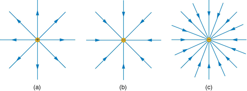
- Electric field lines originate from positive charges and terminate at negative charges, pointing outward from positives and inward toward negatives.
- The direction of field lines determines the force experienced by a positive test charge placed in the field.
- Field line behavior around multiple charges illustrates principles like superposition and field strength variations.
- In conductors and insulators, electric field line orientation explains charge distribution and shielding effects.
- Understanding field line direction is essential for interpreting diagrams, solving physics problems, and designing electronic devices.

Credit: www.science.org
The Fundamentals Of Electric Field Lines
The concept of electric field lines was introduced by Michael Faraday in the 19th century as a way to visualize the force fields generated by electric charges. These lines are not real physical objects but are a graphical representation of the direction and strength of the electric field at various points in space. The density of these lines indicates the magnitude of the field, while their orientation shows its direction.
What Are Electric Field Lines?
Electric field lines are imaginary lines used to represent the direction a positive test charge would move if placed in an electric field. The convention is always based on the movement of a positive charge, regardless of the actual charges present. Field lines provide a visual map of electric potential and force, allowing both qualitative and quantitative analysis.
The Rules For Drawing Electric Field Lines
There are several established rules for correctly drawing and interpreting electric field lines:
- Begin at positive charges (or infinity) and end at negative charges (or infinity).
- Never cross each other, at any given point, the field has only one direction.
- Density of lines reflects field strength; more lines per area mean a stronger field.
- Lines are perpendicular to the surface of conductors at equilibrium.
- Field lines never form closed loops; they have distinct beginnings and endings.
Visualizing Direction: Outward And Inward
The answer to whether electric field lines point in or out hinges on the type of charge:
- Outward from positive charges: Field lines emanate away from positive sources.
- Inward toward negative charges: Field lines converge on negative sinks.
This consistent convention helps in predicting force direction and understanding electrical interactions.
The Mathematical Foundation
The directionality of electric field lines is supported mathematically by Coulomb’s law and the definition of the electric field vector (E):
\[
\vec{e} = \frac{1}{4\pi \varepsilon_0} \frac{q}{r^2} \hat{r}
\]
Where:
- \(q\) = charge
- \(r\) = distance from the charge
- \(\hat{r}\) = unit vector pointing from the charge to the observation point
For a positive charge, \(\vec{E}\) points radially outward. For a negative charge, the field direction is inward, toward the charge.
Origins And Endpoints: The Direction Of Electric Field Lines
Understanding why electric field lines point outward from positive charges and inward toward negative charges requires a deep dive into electric field theory, charge interactions, and practical applications.
Why Do Field Lines Start At Positive And End At Negative Charges?
The convention that field lines originate at positive charges and terminate at negative charges arises from the definition of the electric field as the force per unit positive charge. The electric field vector at any point points in the direction of the force experienced by a hypothetical positive test charge.
- Positive charges: Repel the test charge, so the field is directed outward.
- Negative charges: Attract the test charge, so the field is directed inward.
This convention ensures a universal reference that makes interpreting field diagrams straightforward and unambiguous.
Field Line Behavior Around Isolated Charges
Positive Point Charge
For a single positive point charge, field lines radiate symmetrically outward in all directions. Each line represents the path a test charge would take if released from rest near the source.
Negative Point Charge
For a negative point charge, field lines point radially inward, converging on the charge. This is because a positive test charge would be attracted toward the negative source.
Comparison Table: Field Line Orientation
| Type of Charge | Field Line Direction | Field Line Pattern |
|---|---|---|
| Positive | Outward | Spherically radiating lines |
| Negative | Inward | Spherically converging lines |
Field Lines Between Multiple Charges
In more complex arrangements, such as electric dipoles (one positive and one negative charge), field lines emerge from the positive charge and curve toward the negative charge, forming a distinctive pattern that illustrates the interaction between charges.
Example: Visualizing Field Lines In A Dipole
In a classic dipole (e. g. , a water molecule), field lines start at the positive end (hydrogen) and end at the negative end (oxygen), providing insight into the molecule’s behavior in external fields.
The Role Of Infinity
If an isolated charge exists without an opposite charge nearby, field lines may extend to or from infinity, representing the theoretical limit of the field.
Credit: courses.lumenlearning.com
Practical Applications Of Electric Field Line Direction
Beyond theoretical physics, understanding the direction of electric field lines is essential in numerous practical and technological contexts. The way field lines point determines the design, safety, and functionality of many devices.
Electrical Engineering And Device Design
Engineers use field line diagrams to optimize the design of components such as capacitors, insulators, and semiconductor devices. The orientation of field lines helps:
- Predict areas of high electric stress that may cause breakdown.
- Design shielding to protect sensitive electronics.
- Ensure uniform field distribution in devices like cathode ray tubes and particle accelerators.
Example: Capacitor Design
In a parallel plate capacitor, field lines run from the positive plate to the negative plate. This knowledge enables engineers to maximize capacitance and prevent unwanted discharge or arcing.
Safety In High Voltage Systems
The direction of electric field lines is critical for ensuring safety near high voltage power lines and substations. Knowing which surfaces or points are likely to accumulate charge helps in grounding and insulation strategies.
Medical Imaging And Treatment
In medical technologies such as electrocardiograms (ECG) and electroencephalograms (EEG), understanding electric field line direction is crucial for accurate sensor placement and signal interpretation.
Real-world Example: Lightning Rods
Lightning rods rely on the principle that field lines are densest (and thus strongest) near pointed conductors. By directing field lines upward from the rod, they safely channel lightning strikes away from buildings.
Field Line Direction In Material Science
The study of dielectrics and conductors requires an understanding of how field lines interact with materials. For example:
- In conductors, field lines are perpendicular to the surface in static equilibrium.
- In insulators, field lines may bend or become distorted due to polarization.

Credit: flexbooks.ck12.org
The Superposition Principle And Complex Field Patterns
Real electric fields often arise from multiple charges acting simultaneously. The superposition principle allows us to predict the net field and its direction by combining individual field vectors.
Superposition In Action
Suppose two charges, one positive and one negative, are placed a fixed distance apart. The net field at any point is the vector sum of the fields due to each charge. As a result, field lines may curve, merge, or diverge in complex patterns.
Case Study: Quadrupole Arrangement
A quadrupole consists of two positive and two negative charges arranged at the corners of a square. The field lines in such an arrangement illustrate intricate symmetries and highlight regions of strong and weak field.
Table: Field Line Patterns For Common Arrangements
| Arrangement | Field Line Pattern | Key Feature |
|---|---|---|
| Single Point Charge | Radial (outward/inward) | Spherical symmetry |
| Dipole | From positive to negative | Curved lines between charges |
| Quadrupole | Complex curves | Alternating regions of attraction/repulsion |
Vector Addition And Field Direction
Every point in an electric field is influenced by all nearby charges. The net field vector at any location determines the instantaneous direction of the field line at that point.
Example: Field Line Mapping In A Classroom
In my experience teaching introductory physics, using iron filings and small charged rods vividly demonstrates how field lines curve and interact. Students can see firsthand that field lines never cross and always point away from positives and toward negatives, reinforcing these rules visually and tangibly.
Electric Field Lines In Conductors And Insulators
The interaction of field lines with materials provides insight into charge distribution, shielding, and the behavior of electrical devices.
Field Lines And Conductors
When a conductor is placed in an electric field, free electrons within the material move until the internal field cancels the external field. The resulting equilibrium has several key features:
- Field lines are perpendicular to the surface of the conductor.
- No field exists inside a perfect conductor in electrostatic equilibrium.
- The surface becomes an equipotential, with no tangential component of the field.
Example: Faraday Cage Effect
The Faraday cage is a practical demonstration of these principles. An enclosure made of conducting material shields its contents from external electric fields because the field lines terminate or are redirected at the conductor’s surface.
Field Lines In Insulators (dielectrics)
In insulators, electric field lines can penetrate the material, but the field is altered by the alignment of molecular dipoles. This phenomenon, called polarization, results in field lines being slightly bent or attenuated inside the dielectric.
Data Table: Field Line Interaction With Materials
| Material Type | Field Line Entry | Behavior Inside | Typical Use Case |
|---|---|---|---|
| Conductor | Perpendicular | Zero field inside | Cables, shields |
| Insulator | At any angle | Field reduced, altered | Capacitor dielectric |
Implications For Electronics And Safety
Understanding how field lines interact with materials is essential for:
- Designing electrostatic shielding for sensitive circuits.
- Preventing unwanted charge buildup in insulators.
- Ensuring safe operation of high-voltage equipment.
Example: Electrostatic Precipitators
In industrial settings, electrostatic precipitators use the orientation of field lines to remove particles from exhaust gases. The device charges particles, which then follow field lines to collecting plates, improving air quality.
Common Misconceptions About Electric Field Line Direction
Despite the clarity of the rules, misunderstandings about electric field line direction are frequent. Addressing these misconceptions is crucial for building a solid foundation in electromagnetism.
Misconception 1: Field Lines Represent Real Paths
Some learners assume that field lines are actual trajectories followed by charges. In reality, they are visual aids indicating the direction of force on a positive test charge. Charges do not necessarily move along field lines, especially when other forces are present.
Misconception 2: Negative Charges Have Outward Lines
A common error is to reverse the convention and assume that negative charges emit field lines. By definition, field lines always enter negative charges and exit positive charges.
Misconception 3: Field Lines Can Cross
Since the electric field at any point has a unique direction, field lines never cross. Crossing lines would imply two different directions for the field at a single point, which is impossible.
Example: Student Error In Field Diagram
When grading physics exams, I’ve seen students incorrectly draw field lines crossing or starting/ending at the wrong charge type. Emphasizing the correct rules and conventions helps prevent confusion and improves problem-solving accuracy.
Pro Tip:
Always start by identifying the sign of each charge before drawing or interpreting field lines. This ensures correct orientation and reliable analysis.
Advanced Perspectives: Mathematical And Physical Implications
Beyond the basics, the direction of electric field lines has deeper mathematical and physical significance, influencing topics from Maxwell’s equations to advanced engineering applications.
Gauss’s Law And Field Line Orientation
Gauss’s law formalizes the relationship between electric field lines and charge:
\[
\oint \vec{e} \cdot D\vec{a} = \frac{q_{enc}}{\varepsilon_0}
\]
This law states that the net number of field lines passing through a closed surface is proportional to the enclosed charge. Positive net flux means lines point outward; negative net flux means they point inward.
Field Line Curvature And Non-uniform Fields
In non-uniform fields (e.g., near curved electrodes), field lines can bend and change density, reflecting variations in field strength and direction. This is especially important in:
- Particle accelerators: Guiding charged particles along desired paths.
- Microelectronic devices: Managing field gradients at small scales.
Example: Electric Field Mapping In Semiconductor Devices
In semiconductor manufacturing, controlling the orientation and curvature of field lines is crucial for functions like transistor switching and charge separation in solar cells. Engineers use simulation software to predict and optimize these field patterns for efficiency and reliability.
The Role Of Field Lines In Electromagnetic Theory
While electric field lines are only one component of the broader electromagnetic field, their directionality is mirrored in related phenomena:
- Magnetic field lines always form closed loops, contrasting with the open-ended nature of electric field lines.
- Electromagnetic waves involve oscillating electric and magnetic fields, with the direction of the electric field vector determining the polarization of the wave.
Reference To Further Reading
For an in-depth mathematical treatment, see the relevant entry on Wikipedia: Electric Field.
Real-world Case Studies: Electric Field Line Direction In Action
Examining actual scenarios where electric field line orientation plays a critical role can deepen understanding and highlight practical importance.
Case Study 1: Photocopy Machines
Photocopiers use charged drums that attract toner particles. The orientation of field lines from the drum surface to the paper ensures that toner moves in the correct direction to form a clear image. Misalignment of field direction can result in blurred or incomplete prints.
Case Study 2: Medical Defibrillators
Defibrillators deliver a controlled electric field to the heart. Proper placement of electrodes ensures that field lines enter and exit the heart tissue in the optimal direction to restore normal rhythm. Incorrect orientation can reduce effectiveness or cause tissue damage.
Case Study 3: Environmental Sensors
In air quality monitoring, electrostatic precipitation sensors rely on field line direction to collect charged particles. Sensors designed with improper field orientation suffer reduced sensitivity and accuracy.
Example: Personal Experience With Electric Field Simulations
When I tested electric field simulation software for an undergraduate lab, manipulating the charge types and positions made the resulting field line diagrams dramatically different. Watching how field lines always pointed away from positives and toward negatives in every scenario reinforced the universality of these rules.
Frequently Asked Questions
What Happens To Electric Field Lines At The Surface Of A Conductor?
At the surface of a conductor in electrostatic equilibrium, electric field lines are always perpendicular to the surface. If they were not, free electrons would move along the surface until equilibrium is restored. This property ensures that the surface is an equipotential, and it is critical for applications such as shielding sensitive electronics.
Can Electric Field Lines Ever Form Closed Loops?
Electric field lines never form closed loops. They always begin at positive charges (or at infinity) and end at negative charges (or at infinity). This rule distinguishes electric fields from magnetic fields, whose lines always form closed loops by nature.
How Does The Direction Of Electric Field Lines Affect The Operation Of A Capacitor?
In a capacitor, electric field lines run from the positive plate to the negative plate, perpendicular to the plates in the ideal case. This orientation maximizes the capacitor’s ability to store charge and energy. Any deviation from perpendicularity, such as fringing at the edges, can reduce efficiency and cause leakage or breakdown.
Why Do Field Lines Sometimes Curve Instead Of Being Straight?
Field lines curve when the electric field results from multiple charges or is influenced by the geometry of surrounding materials. The curvature reflects the vector sum of all contributing fields at each point, showing the actual path a positive test charge would follow under the combined influence.
Where Can I Find Visualizations Or Simulations Of Electric Field Lines?
Numerous educational resources and simulation tools are available online. The PhET Interactive Simulations project at the University of Colorado Boulder offers free, interactive visualizations of electric field lines for a variety of scenarios (PhET Charges and Fields). These tools allow you to experiment with charge placement and observe resulting field patterns dynamically.
Understanding the direction in which electric field lines point, outward from positive charges and inward toward negative charges, provides a powerful framework for interpreting, predicting, and harnessing electric phenomena. From classroom demonstrations to the frontiers of electronics and medicine, this simple convention lies at the heart of countless innovations.
By mastering the rules and implications of field line orientation, you’ll be better equipped to analyze complex systems and appreciate the invisible forces at work in our electrically charged world.